Make your own Partner N64 console, for use with IS Viewer
“How to get your N64 Mature”
The final guide to your very own KµC N64 by Kammedo / ConsoleFun, (c) 2007
Introduction
Coding on the N64 requires lots of ressources, the mostly one in the form of money (and time), because of parts of dev systems you need to get together (and comfortable with) in order to be able to develope your own games on it. The one who wants to code on the N64 has two choices : either use a non official kit not featuring important options (like great 64dd support) or getting an official one, with all options but whose cheapness is, well, not that cheap. The Partner N kit is one of those. The Partner N kit is usually composed of :
- one (sometimes two) Partner N ROM Emulators (=Partner N Carts) + CD with Partner N software (debugger)
- ISA / PCI control interface card
- KµC N64
- N64 Software Developement kit (commonly 5 CDS: OS PC, OS SGI, Dev Tools, Online Manuals, Developer Doc)
- Documentation (One or two books depending if you have the blue 64DD drive too : Partner N and 64DD Docs)
What do I need?
Proper screwdrivers – the special 4,5 mm version of he Nintendo “gamebit” An XActo type knife for lifting pins Some AWG 32 cables (25-40 cm will do the job) Soldering Iron + flux Patience A firm hand Note : even being the soldering actions very easy and of reduced dimensions, it is important to have at least some experience with soldering, especially on SMD parts. You can easily find tutorials about this on the net. The mod has been performed on a NUS-CPU-04 model N64, which is similar (and thus compatible) with models NUS-CPU-03 and NUS-CPU (P)-01. All N64s have (a) CPU, (b) PI, (c) PIF and (d) reset switch, so it is also garanteed that they can all be modified! But the pictures you see here cannot be used on any different models than the three listed here.
Ok, I have everything! now how should I put all that crap to use?
Carefully take the Memory Expansion pak off if you have any inserted. Open the N64 with the special screwdriver. There are 5 of them on the back of it that need to be removed. You can easily find a guide on the net that show you how if you dont know what we are talking about here. After having taked off the plastic overyou’ll find yourself in front of this :
figure 3.1
Dont get scaried by that, its only a (massive) cooler. Just get all screws off, starting from the top. Remember the position of those screws. Not all of them fit in every hole, and if you want to have your N64 as you had it before opening it, you should care. Take the metal plates off as they get loose once you lift the screws away. And you’ll see.. the internal frequecency shielding of the N64 entirely! Carefully lift it from the rest. It may be hard to find a point where to lift it, but it gets away easily. So be prepared to meet the N64 in its very own fashion.figure 3.2
There you have a CPU, a RCP, and two RDRAM chips each 2MB. Well, you dont see them because of the heat dissipators on them. But they are there, just believe it. This guide (as stated) was realized on a N64 NUS-CPU-04 model. Other models could be compatilbe with the mod but that hasnt been prooved yet. We are now going to so something you should never try on your SNES, or any other console. Put your hands on the sides of the cart connector and slowly lift it from the board. Dont worry, its going to get off with just a bit of pushing. After you took off the connector, lift the N64 Board, and put it near the case.figure 3.3
There. That was it for the opening.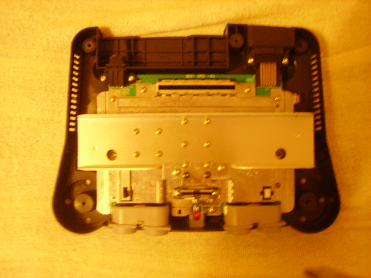
figure 3.1
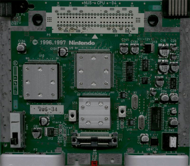
figure 3.2
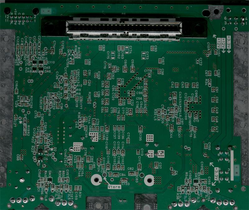
figure 3.3
Wow. This looks pretty cool! And now?
We are not going to alter the N64 much. Remember, it should still be functional after the mod. The modification consists of: A. removing three signals from pins on PI bus B. wiring up new debugging related signals to these three pins The signals that are removed from the PI:
PI pin 24 – “left audio”
PI pin 46 – “video”
PI pin 49 – “right audio”
CPU pin 28 – “int 4”
PIF pin 8 – “enable”
Reset – “warm reset” (aka. reset button signal)
PI_24 = CPU_28
PI_46 = reset
PI_49 = PIF_8
Disabling The Signals
PI_46 in this retail N64 is connected to U4 pin 12. U4 is also known as VDC-NUS aka the video DAC. You need to cut the trace going to PI_46. We located the trace just above C130 in this photo:
figure 5.1
Cut the trace, as shown in the photo below. PI_46 can then be used for other things.figure 5.2
PI_24 and PI_49 are used for left and right audio (if the cart has special analog audio circuits inside). These signals are handled by the AMP-NUS chip in a retail N64, and on their way to the AMP-NUS these signals go through R21/C30 and R17/C29 respectively. Removed these signals by desoldering the four SMD components R21, C30, R17 and C29 on the back side of the PCB:figure 5.3
After desoldering you have a total of 8 clean pads (two rows of four):figure 5.4
We name these 8 pads in the rest of the guide: a b c d e f g h Now you have PI_24, PI_46 and PI_49 ready for alternative use.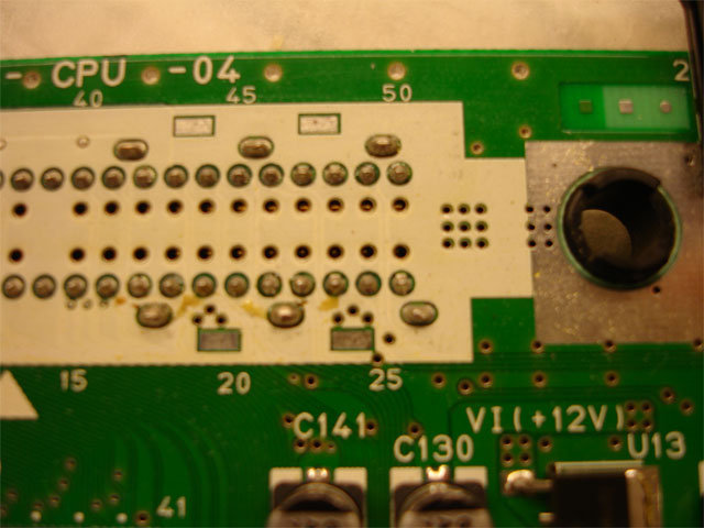
figure 5.1
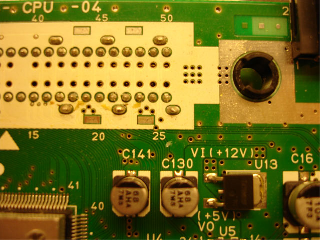
figure 5.2
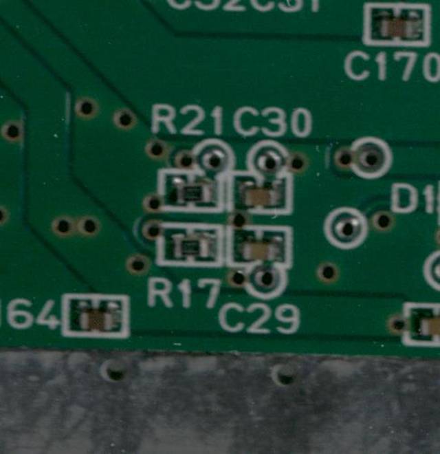
figure 5.3
figure 5.4
Hooking up the Partner N Signals
To hook up the new signals we used AWG 32 wire. If you want have wires going through the small via holes in the PCB like we did, you might want to use wire that is even thinner. It was really tight. CPU_28 goes to pad “f” through the bigger via hole right of the „30†label. Measure the wire length you need. Then lift CPU pin 28 from the PCB with an X-Acto type knife, like shown here:
figure 6.1
Solder a piece of wire to it:figure 6.2
PIF_8 goes to pad “c”. It turns out PIF_8 is also connected to U3 pin 4, so if you want you can solder the wire going to pad “c” to U3_4 like this, and plug it in the nearest via hole:figure 6.3
PI_46 goes to reset. Solder a piece of wire to it like this:figure 6.4
Then look it up to reset button like shown here (upper right corner):figure 6.5
Solder the wires going from CPU_28 and U3_4 (same as PIF_8) to pads “f” and “c” respectively, like shown here:figure 6.6
There : a simple way to transform your retail N64 in a fully compatible KµC N64! 😀
figure 6.1
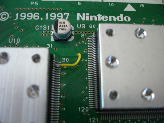
figure 6.2

figure 6.3
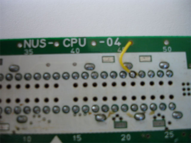
figure 6.4
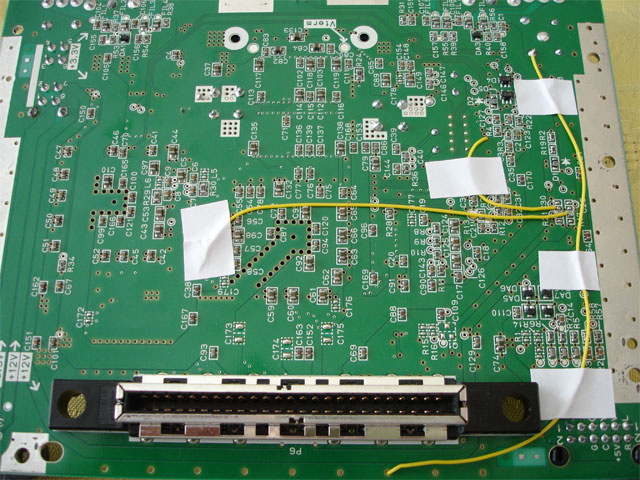
figure 6.5
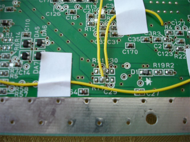
figure 6.6
Credits & Copyright Stuff
Authors:
ConsoleFun, kammedoThanks to:
Crazynation for pinouts (www.crazynation.org) The guys over at ASSEMBLERGames, the most obscure place of the net!Hosted by:
ultra64.ca, with permission from kammedoCopyright:
The usual : Every Mark is TM of the respective company. Modding is made at you own risk, and thus we cant be held responsible for you causing damage to your N64.© 2019 ultra64.ca. All Rights Reserved.